Introduzione
Use this guide to replace the trackpad in a 2019 MacBook Air.
-
-
If your MacBook is running Big Sur v11.1 or later, disabling Auto Boot may not work. You can proceed normally, but make sure to disconnect the battery as soon as you're inside.
-
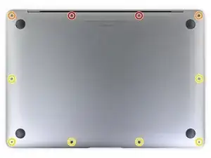
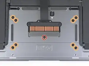
Use a P5 driver to remove the following screws:
-
Two 7.9 mm screws
-
Two 7.1 mm screws
-
Six 2.6 mm screws
-
-
-
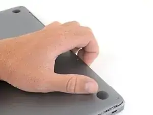
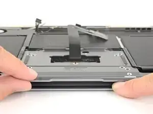
Wedge your fingers between the display and the lower case and pull upward to pop the lower case off the Air.
-
Remove the lower case.
-
-
-
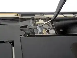
Peel back the tape covering the battery connector enough to reveal the connector underneath.
-
-
-
Use a spudger to slide the battery connector parallel to the logic board and out of its socket on the logic board.
-
-
-
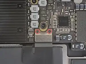
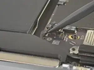
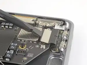
Use a T3 Torx driver to remove the two 1.4 mm screws securing the trackpad connector bracket.
-
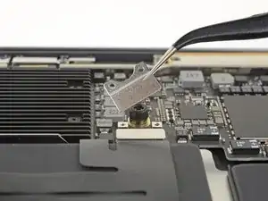
Remove the trackpad connector bracket.
-
-
-
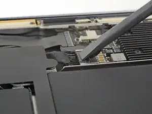
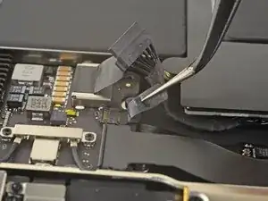
Slide the tip of a spudger underneath the left speaker cable and pry straight up to disconnect the speaker.
-
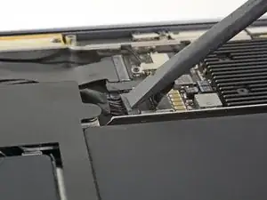
With the connector disconnected, slide the flat end of a spudger under the cable to separate the adhesive securing the cable to the logic board.
-
-
-
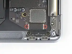
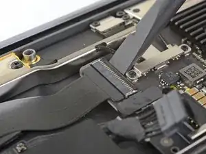
Use a T3 Torx driver to remove the two 1.3 mm screws securing the USB-C port connector bracket.
-
Remove the USB-C connector bracket.
-
-
-
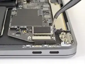
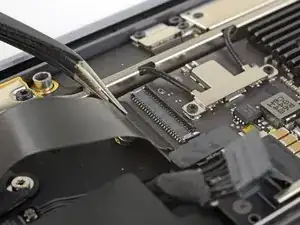
Use the flat end of a spudger to pry the USB-C cable connector up and out of its socket on the logic board.
-
-
-
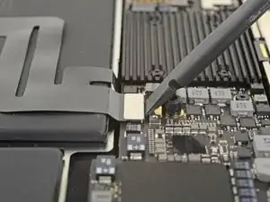
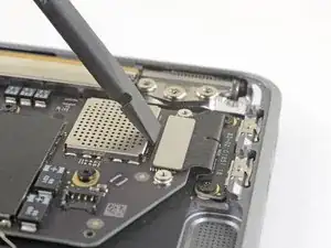
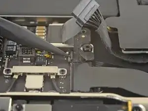
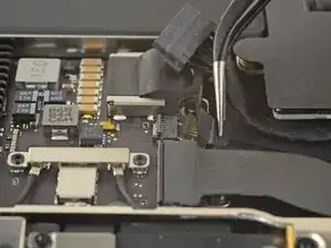
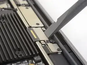
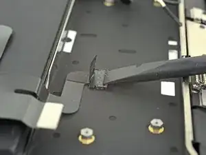
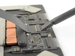
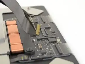
Use a spudger to lift up the small locking flap on the sound board cable's ZIF connector.
-
Slide the sound board cable out of the ZIF connector.
-
-
-
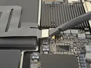
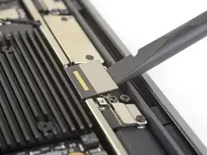
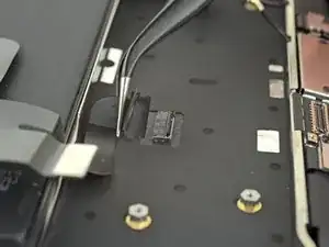
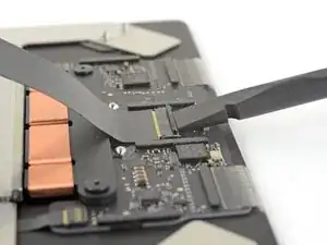
Use the tip of a spudger to lift up the locking flap on the fan cable's ZIF connector.
-
Slide the fan cable out of the ZIF connector.
-
-
-
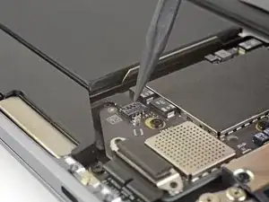
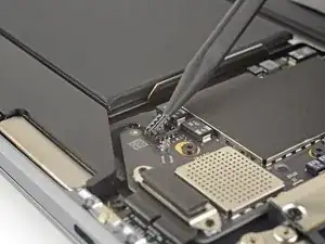
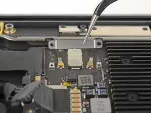
Use a T3 Torx driver to remove the two 1.4 mm screws securing the antenna cable bracket.
-
Remove the antenna cable bracket.
-
-
-
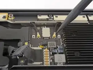
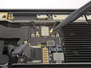
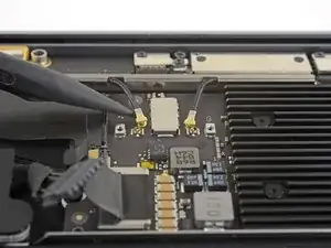
Insert the point of a spudger under one of the antenna cables close to the connector. Pry straight up to disconnect the cable.
-
Repeat for the other antenna cable.
-
-
-
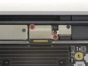
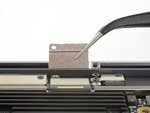
Use a T3 Torx driver to remove the two 1.5 mm screws securing the display cable connector bracket.
-
Remove the display cable connector bracket.
-
-
-
Use a T5 Torx driver to remove the following screws:
-
One 5.5 mm screw
-
Three 2.6 mm screws
-
Two 1.9 mm screws
-
-
-
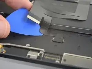
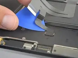
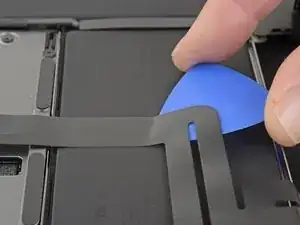
Carefully slide an opening pick under the trackpad cable to separate the adhesive securing it to the upper case.
-
-
-
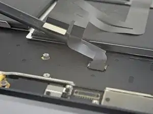
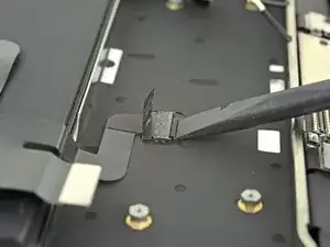
Use the flat end of a spudger to lift the small locking flap on the trackpad ZIF connector.
-
Slide the trackpad cable straight out of its connector.
-
-
-
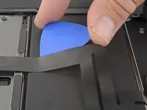
Carefully slide an opening pick under the trackpad cable to separate the adhesive securing it to the battery.
-
-
-
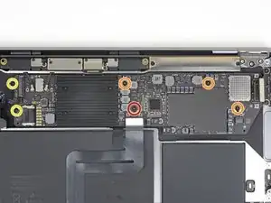
Use a T5 Torx driver to remove the following screws securing the trackpad:
-
One 3.2 mm screw
-
Eight 3.1 mm screws
-
-
-
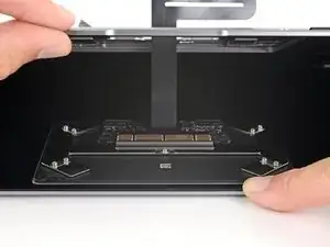
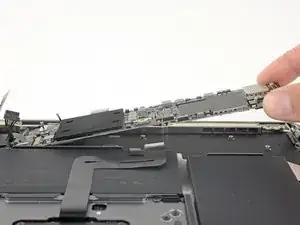
With the laptop still lying screen-side down, carefully open the laptop. The trackpad will stay sitting on the display.
-
Remove the trackpad from the MacBook. Take care not to scratch the display.
-
-
-
Use the flat end of a spudger to lift the small locking flap on the trackpad's ZIF connector.
-
Slide the trackpad cable straight out of the ZIF connector.
-


Compare your new replacement part to the original part—you may need to transfer remaining components or remove adhesive backings from the new part before installing.
To reassemble your device, follow the above steps in reverse order.
Take your e-waste to an R2 or e-Stewards certified recycler.
Repair didn’t go as planned? Check out our Answers community for troubleshooting help.

If the first thing you do is disconnect the battery, is it really an issue if you don’t (or can’t) disable auto-boot?
maccentric -
I agree, why disable Auto-Boot when the lid is closed and the battery is disconnected immediately? – I've never had an issue since 2016 when the feature was introduced.
stevebsiegel -
On my machine, the longest two screws were in the corners, while the other two long screws were in the middle. Perhaps previous service in the past had them replaced into the wrong place? In any case, the longest screws do seem to fit in either place. I guess 0.8mm is not very much of a difference. Seems like poor design if they could have used one size of screw.
johann beda -
Just did one, and it also had longest screws in the corners.
maccentric -
Just did another, and the long ones were in the middle. Definitely poor design and quality control.
maccentric -