Introduzione
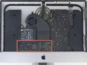
Questa guida mostra come rimuovere la scheda madre dell'iMac Retina 4K 2017.
Alcune immagini in questa guida usano un iMac 2015, che ha alcune differenze visive minori. Queste differenze non influiscono su questa procedura.
Questa guida è valutata come "potenzialmente pericolosa" poiché richiede di maneggiare un alimentatore che contiene condensatori ad alta carica. Scollega l'iMac dalla corrente e tieni premuto il tasto di accensione per almeno 10 secondi per lasciar scaricare i condensatori. Tocca la scheda solo sui bordi e non toccare le componenti saldate.
-
-
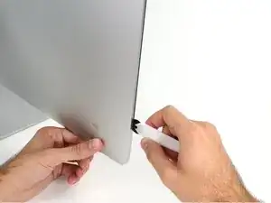
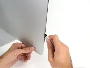
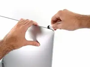
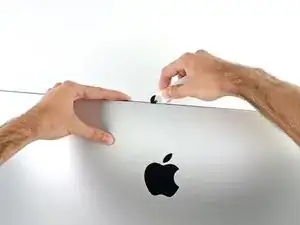
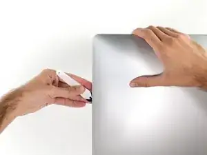
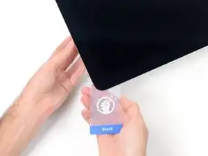
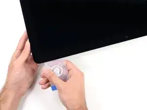
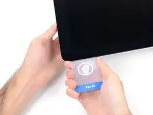
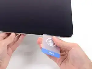
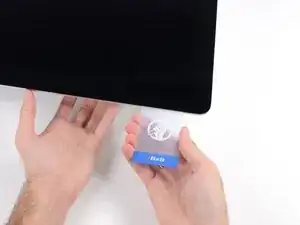
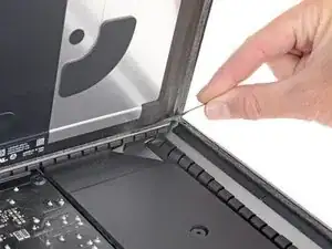
Iniziando sulla parte sinistra del display, accanto al pulsante di alimentazione, inserire l'attrezzo per l'apertura dell'iMac nello spazio fra il pannello di vetro e il case posteriore.
-
-
-
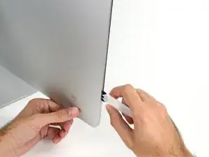
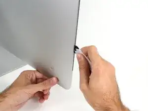
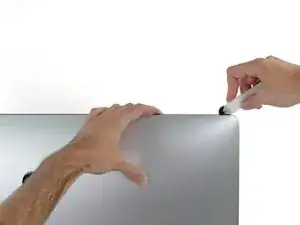
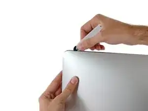
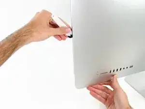
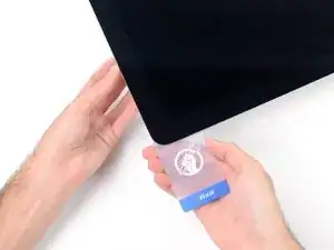
Utilizza l'attrezzo come una rotella tagliapizza: fallo scorrere nella feritoia e taglierà a metà le strisce adesive in schiuma.
-
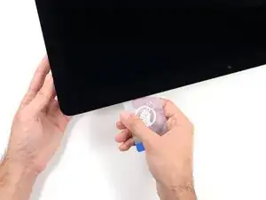
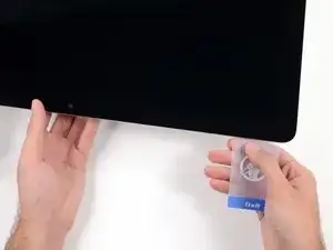
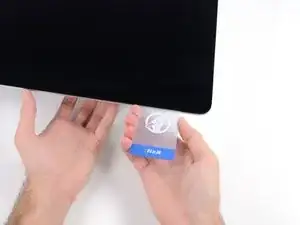
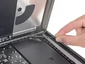
Usa l'attrezzo lungo il lato sinistro del display.
-
-
-
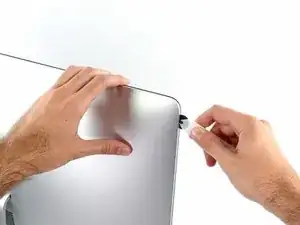
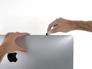
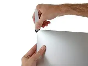
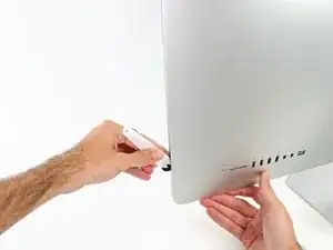
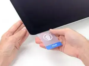
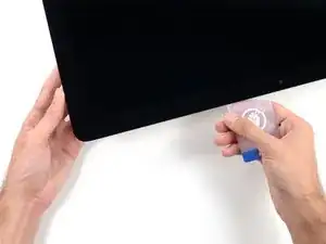
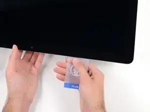
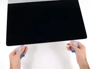
Continuare lungo la parte superiore del display.
-
È consigliabile far scorrere ripetutamente l'attrezzo avanti e indietro lungo la parte già tagliata, per fare in modo di separare il più possibile l'adesivo.
-
-
-
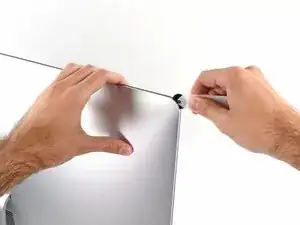
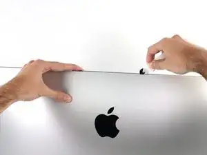
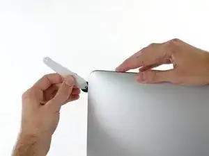
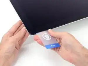
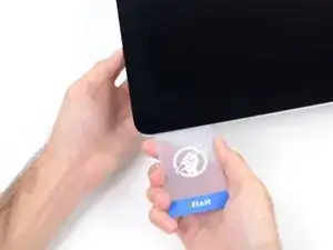
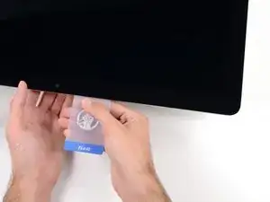
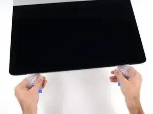
Terminare l'applicazione dell'attrezzo per l'apertura nella parte inferiore del lato destro del display.
-
-
-
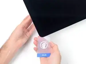
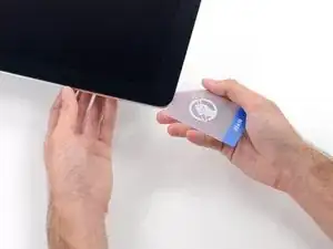
A partire dall'angolo superiore destro dell'iMac, inserire una scheda di plastica fra il display e il telaio.
-
-
-
Ruotare delicatamente la scheda di plastica per aumentare lo spazio fra il display e il telaio.
-
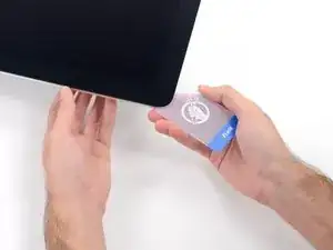
Eseguire movimenti lenti, facendo attenzione a non fare troppa pressione sul vetro del display, poiché occorre solo uno spazio di circa 0,63 cm.
-
-
-
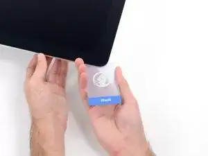
Inserire nuovamente la scheda nell'angolo e lasciarla in sede per evitare che l'adesivo si riattacchi.
-
-
-
Inserire una seconda scheda nello spazio fra il display e il telaio nell'angolo superiore sinistro.
-
-
-
Ruotare delicatamente la scheda per aumentare leggermente lo spazio fra il display e il telaio.
-
-
-
Far scorrere la scheda di plastica verso il centro, fermandosi nuovamente prima della fotocamera iSight.
-
-
-
Mantenendo le schede inserite vicino agli angoli come indicato, ruotarle delicatamente per aumentare lo spazio fra il display e il case.
-
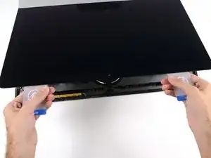
Iniziare a sollevare la parte superiore del display dal telaio.
-
-
-
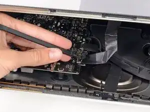
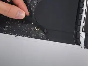
Mantenendo sollevato il display con una mano, utilizzare l'altra per scollegare il cavo di alimentazione.
-
-
-
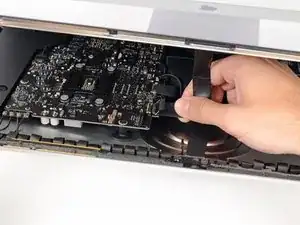
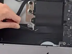
Ruotare verso l'alto la staffa metallica di fissaggio sul cavo dati del display.
-
Scollegare il cavo dati del display.
-
-
-
Prendi la piccola aletta all'estremità di una delle strisce adesive ai bordi inferiori dello schermo e tirale verso la parte superiore dell'iMac per rimuoverla.
-
Ripeti questo passaggio con l'altra striscia adesiva e rimuovila.
-
-
-
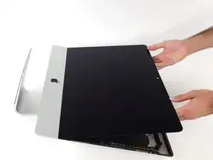
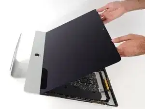
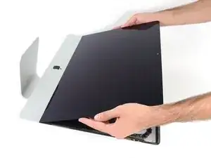
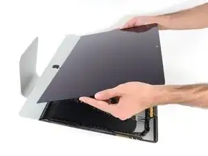
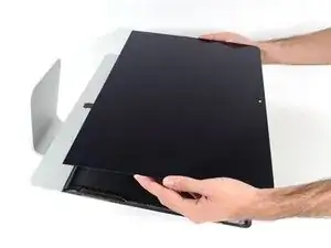
Solleva il display dal telaio e rimuoverlo dall'iMac.
-
Potrebbe essere necessario sollevarlo lentamente da un lato per liberarlo dall'adesivo restante.
-
-
-
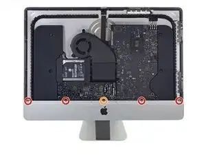
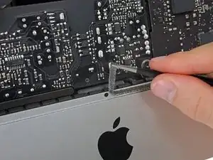
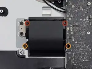
Svita le seguenti viti a croce Phillips che tengono ferma la staffa di supporto inferiore:
-
Quattro viti da 3,2 mm
-
Una vite da 1,7 mm
-
-
-
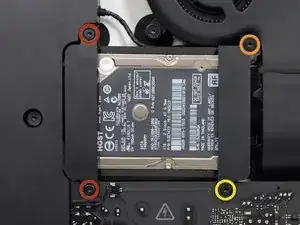
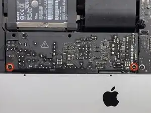
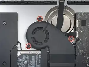
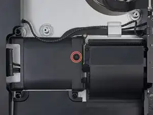
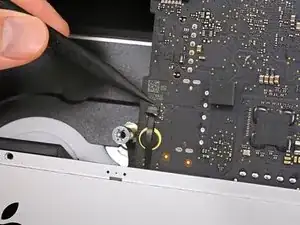
Rimuovi le seguenti viti Torx T10 che tengono ancorato il supporto del'hard drive sull'iMac:
-
Due viti da 21 mm
-
Una vite da 9 mm
-
Una vite da 27 mm
-
-
-
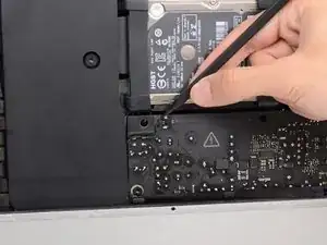
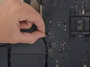
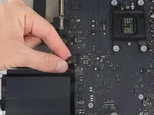
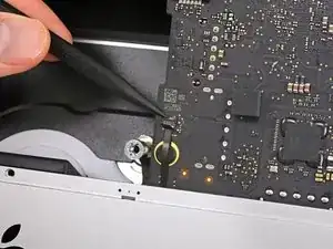
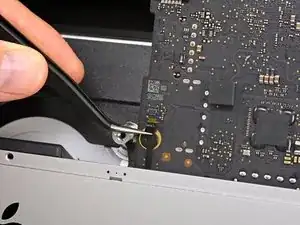
Usa la punta di uno spudger per spingere su un lato alla volta del connettore del cavo del tasto di accensione e scollegalo lentamente dalla sua presa.
-
-
-
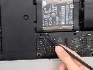
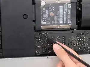
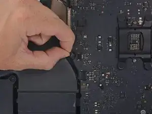
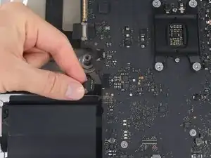
Usa la punta di uno spudger per spingere su un lato alla volta del connettore del cavo di controllo dell'alimentatore e scollegalo lentamente dalla sua presa.
-
-
-
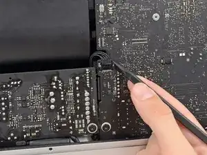
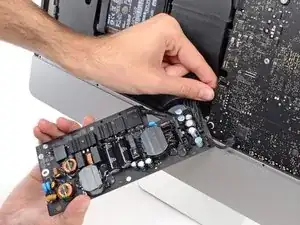
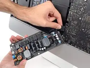
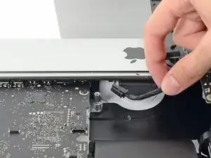
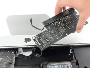
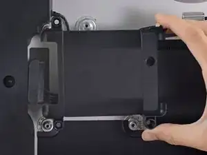
Tira leggermente l'alimentatore verso l'alto e fuori dalla scocca.
-
Ruota l'alimentatore in senso antiorario, sollevando il lato destro di circa 2 cm rispetto a quello sinistro.
-
-
-
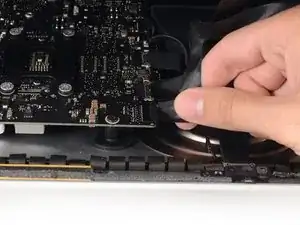
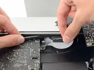
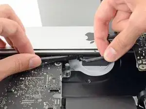
Schiaccia l'aletta sul retro del connettore del cavo di alimentazione e sfilalo dalla sua presa sulla scheda madre.
-
-
-
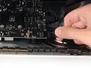
Usa l'estremità piatta di uno spudger per premere verso l'interno l'aletta sul lato del connettore del cavo di alimentazione AC.
-
Mentre premi l'aletta per il rilascio, afferra il cavi di alimentazione AC e sfilalo dalla sua presa.
-
-
-
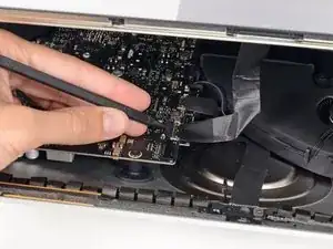
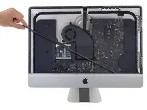
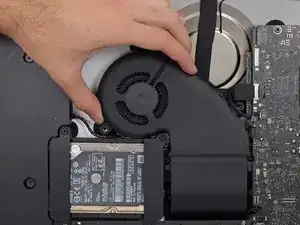
Delicatamente scollega il connettore del cavo della ventola dal suo alloggiamento sulla scheda logica.
-
-
-
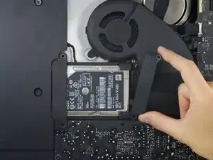
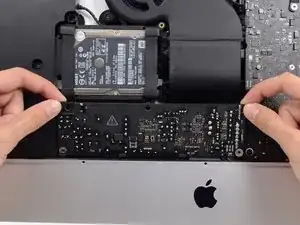
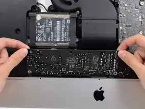
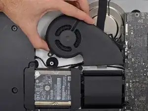
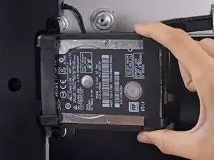
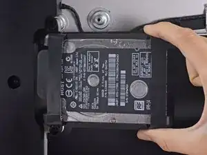
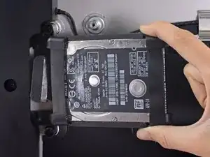
Solleva l'hard drive dal lato più vicino alla scheda madre e tiralo leggermente fuori dal suo alloggio.
-
-
-
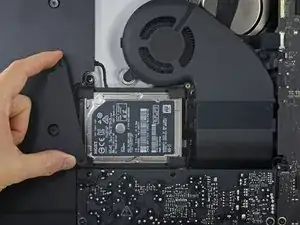
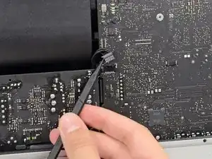
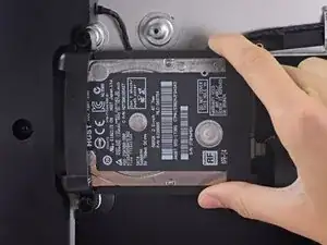
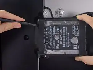
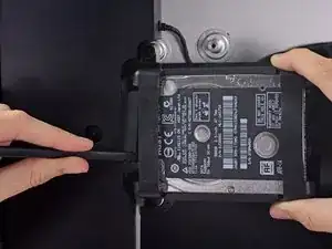
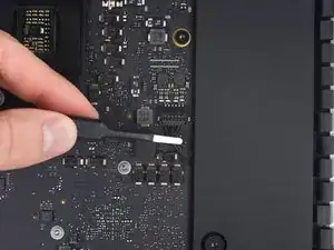
Usa uno spudger per scollegare il cavo dati/alimentazione SATA facendo leva delicatamente su entrambi i lati del connettore per farlo scorrere lontano dall'unità.
-
-
-
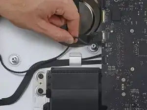
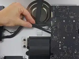
Tira delicatamente verso il basso il cavo di connessione dello speaker di destra finché non viene scollegato dalla sua presa sulla scheda.
-
-
-
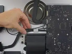
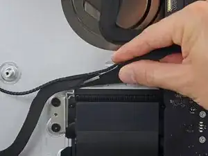
Tira delicatamente fuori dalla sua presa sulla scheda il cavo di connessione dello speaker di sinistra.
-
-
-
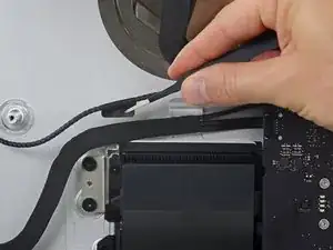
Rimuovi il cavo dello speaker di sinistra dalla clip di fissaggio sul retro della copertura posteriore tirandolo verso l'alto.
-
-
-
Similmente a quanto fatto prima, rimuovi anche i cavi SATA e di alimentazione dalla clip di fissaggio tirando verso l'alto.
-
-
-
Solleva il pezzo di nastro che collega il cavo dello speaker di sinistra ai cavi di alimentazione e connessione SATA.
-
-
-
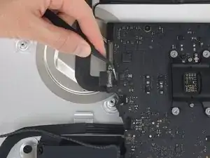
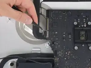
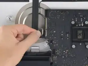
Ruota la staffa di fissaggio sul connettore del cavo della camera FaceTime.
-
Tira il cavo della camera FaceTime fuori dalla sua presa sulla scheda.
-
-
-
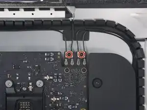
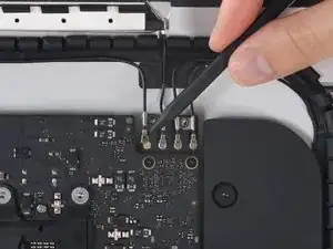
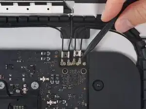
Rimuovi le due viti Torx T5 da 4,0 mm che tengono fermi i quattro cavi delle antenne AirPort/Bluetooth.
-
-
-
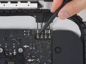
Scollega tutti e quattro i cavi delle antenne tirandoli fuori dalle loro prese sulla scheda Airport/Bluetooth.
-
-
-
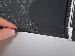
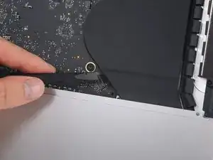
Usa la parte piatta di uno spudger per scollegare il connettore della porta jack dalla sua presa sulla scheda.
-
Delicatamente piega il cavo verso lo speaker in modo che non possa interferire con la scheda.
-
-
-
Rimuovi le seguenti viti Torx T8 che uniscono il condotto di scarico dell'aria alla copertura posteriore:
-
2 viti da 6,2 mm
-
2 viti da 4,7 mm
-
-
-
Solleva e scollega l'aletta di bloccaggio del connettore ZIF del microfono dalla presa sulla scheda e sfila il cavo dal suo zoccolo sulla scheda logica.
-
-
-
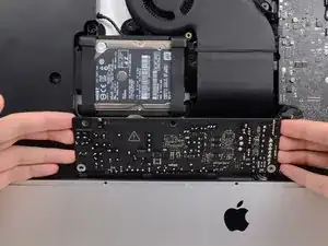
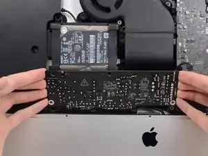
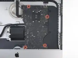
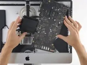
Rimuovi le 4 viti Torx T8 da 7,3 mm che fissano la scheda logica alla copertura posteriore.
-
-
-
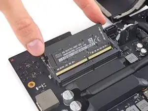
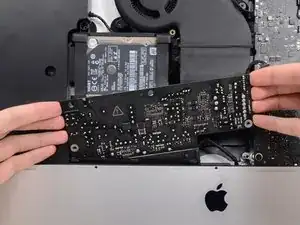
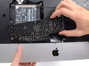
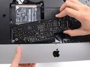
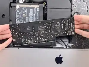
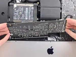
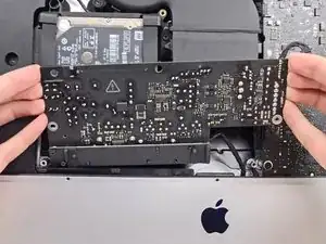
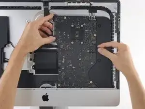
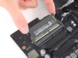
Manovrando la scheda logica solo sui bordi, rovesciala per avere accesso ai due moduli RAM.
-
-
-
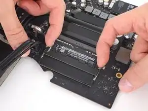
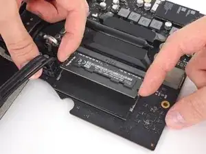
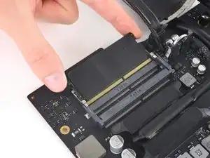
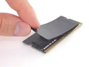
Due alette di bloccaggio, una per lato, mantengono fisso ogni banco di RAM. Usando le dita, spingile verso l'esterno dal primo banco di RAM.
-


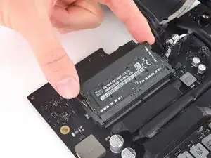
Per riassemblare il tuo iMac, segui le istruzioni di questa guida al contrario.

77 commenti
An excellent guide - many thanks. The logic board was tricksy to get out - the card reader was jamming on the casing, but it came out with care. It's easy to trap the microphone cable and the power button cables when re-assembling, so they're worth looking out for. Successfully replaced the RAM and installed an SSD at the same time - many thanks.
Can a SSD or fusion drive be put in the place where the normal hard drive was?
An ssd can yes - that's what I did at the same time as upgrading the ram. As long as it's a 2.5" ssd it should be fine. The Samsung ssd I used was a but thinner than the hard drive that came out but that doesn't affect anything really. You'll need to either have a bootable clone of your drive, or install Sierra from a USB stick you've already prepared (which is what I did).
A Fusion drive is the terminology used by Apple when the use a board soldered 120ish Gb storage and a standard 1Tb 2.5 inch drive, and bind them together, if you throw in a 1Tb SSD in place of the existing standard hard drive you end up with 2 drives when you begin installation, you can find the instructions to merge the onboard and the new SSD back together again, and boy does it transform these machines, absolute pig with a factory fusion setup.
I also upgraded my hard-drive to a 512 GB Samsung SSD successfully along with installing the 32 GB of RAM. The guide was great, but I have a two comments.
1) The screws that hold the antenna connectors (Step 52) are were very tightly screwed into the board, and it is easy to strip the head of the screw. I stripped one of the screws… Luckily, it was easy to just pull up on the bluetooth/AirPort card and slide it out from its slot on the main board. Thus, an option to removing all the antenna wires, is to just pull the bluetooth/Airport card out. It was quite easy to slip back into the correct spot when reassembling as well.
2) It was only after I completed the repair that I realized that the top of the nice screwdriver provided in the repair kit contained more hidden bits!
I have (21.5 inch, mid 2017, 2.3 ghz) base model same as this but not 4k. How much max ram can I install in my iMac??
Narendra Verma -
This guide contains many extra steps for what should be a straight forward, simple parts replacement without disturbing more than the display, left hand speaker and removal of 4 logic board screws for play. Nothing else except for the left hand speaker wire & iSight cable from logic board, the lower support bracket and loosening the speaker so as to move it around a bit.
For the ram, I bent a pair of cheap tweezers long ago supplied with these replacement kits to the perfect angle for holding, locating and inserting the ram into the slots under the logic bd after moving each retainer w/spudger and popping out the old. Pay attention to the orientation of the ram when removing/inserting the ram! An automotive mirror is handy along with a small flashlight for closeups. Once the ram is aligned properly substitute your fingers for the tweezers, ease it into the slot, push up & engage! Reinstall screws and all else. I have done this job successfully this way countless times. For a tweezers pic contact me!
Ross Elkins -
Additionally, if a blade is present, I install the OSx system on the blade and everything else, apps and home folders on the new SSD. You get the very fast boot off of the blade and the full ssd for all else!
Ross Elkins -