
Introduzione
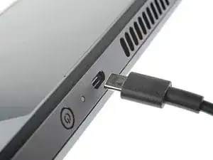
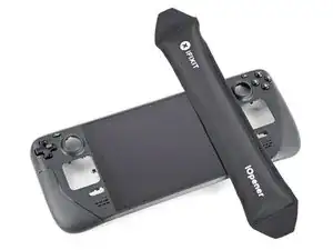
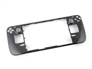
Usa questa guida per rimuovere o sostituire la scocca (cover) anteriore su uno Steam Deck LCD.
Ricorda: segui le procedure generali di sicurezza contro le scariche elettrostatiche (ESD) durante la riparazione del tuo dispositivo.
Questa procedura richiede uno smontaggio quasi completo, inclusa la rimozione dello schermo! Sii consapevole di quello che stai per fare. Ti servirà dell'adesivo di ricambio per lo schermo e per gli altoparlanti.
-
-
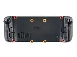
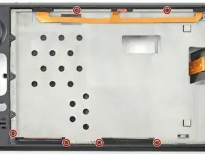
Usa un cacciavite a croce Phillips per rimuovere le otto viti che tengono fermo il pannello posteriore:
-
Quattro viti da 9,5 mm a filettatura grossa
-
Quattro viti da 5,8 mm a filettatura fine
-
-
-
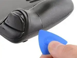
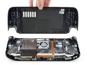
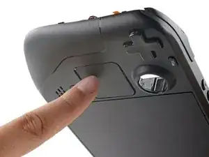
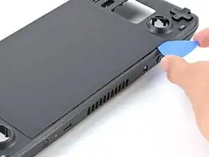
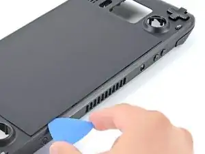
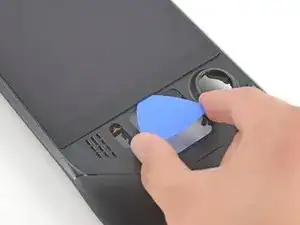
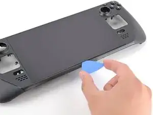
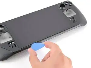
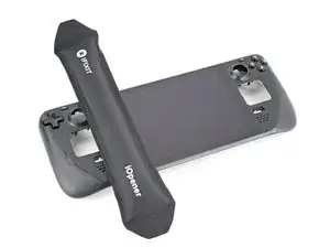
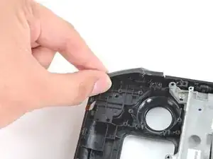
Inserisci un plettro di apertura nella fessura sottile tra la cover posteriore e il guscio frontale, lungo il bordo dell'impugnatura destra.
-
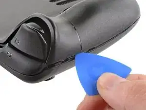
Fai leva sulla cover posteriore per sganciare le clip di bloccaggio.
-
-
-
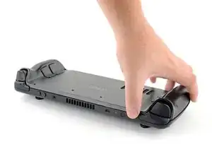
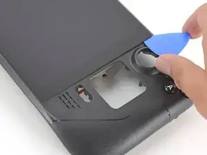
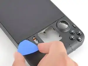
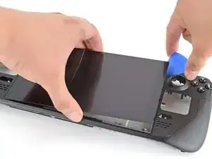
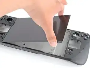
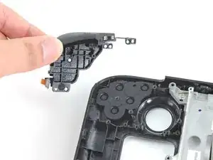
Afferra la cover posteriore dall'apertura che hai appena creato e sollevala e allontanala dal dispositivo per sganciare le clip sui lati lunghi.
-
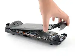
Rimuovi la cover posteriore.
-
-
-
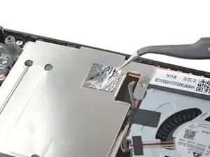
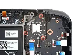
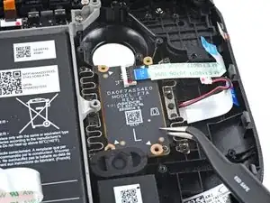
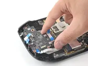
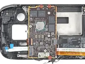
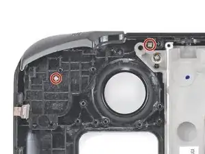
Se possiedi una versione aggiornata dello Steam Deck con la copertura nera della scheda madre, salta questo passaggio.
-
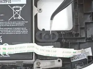
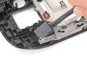
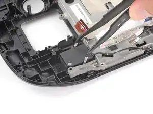
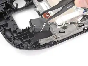
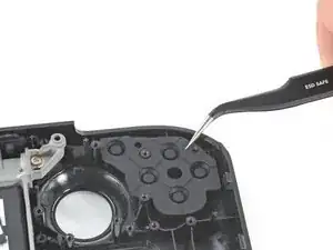
Usa un paio di pinzette per rimuovere il pezzo di foglio d'alluminio che copre la vite nascosta sulla protezione della scheda madre.
-
-
-
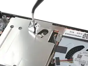
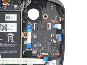
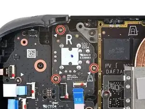
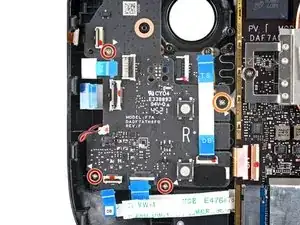
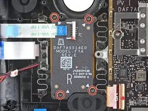
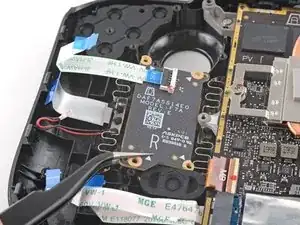
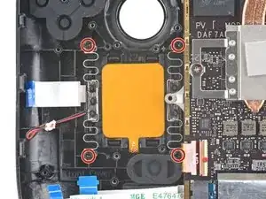
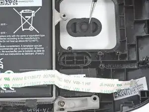
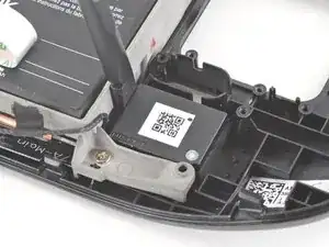
Usa un cacciavite a croce Phillips per rimuovere le tre viti che tengono ferma la protezione della scheda:
-
Una vite da 3,4 mm
-
Due viti da 3,7 mm
-
-
-
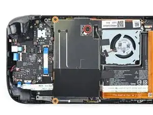
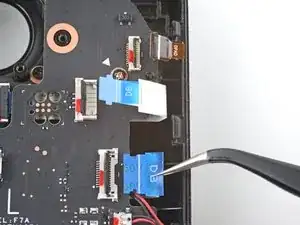
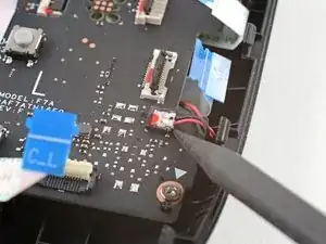
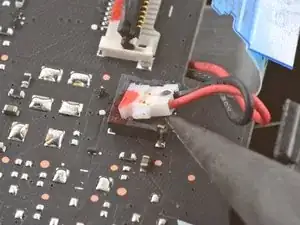
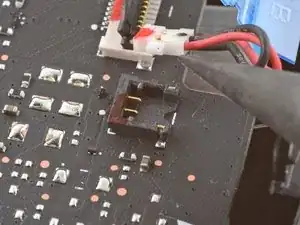
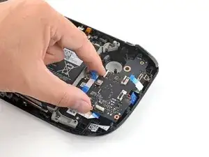
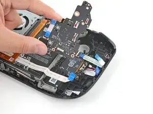
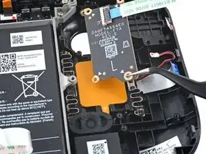
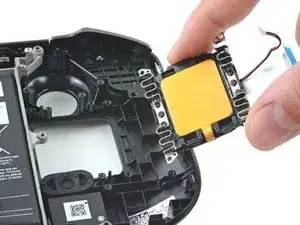
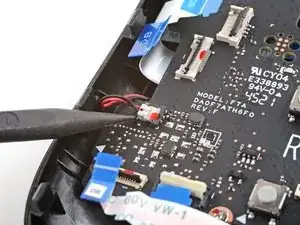
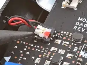
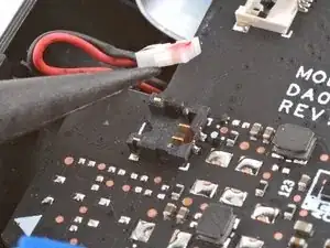
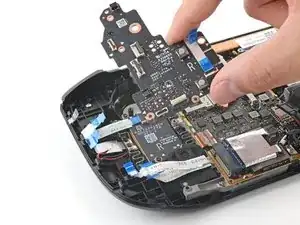
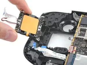
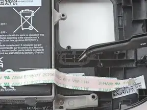
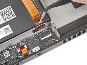
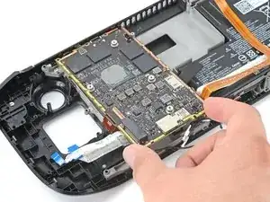
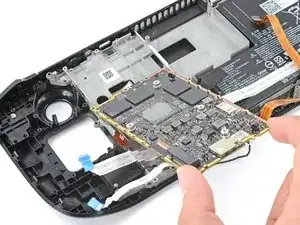
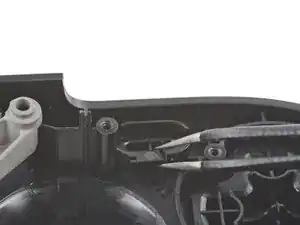
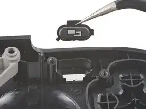
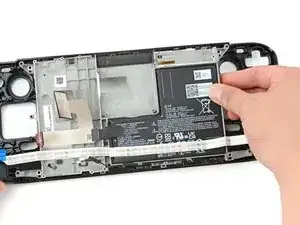
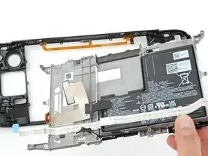
Prendi il cavo della batteria dalla sua linguetta e tiralo via dalla scheda madre per scollegarlo.
-
-
-
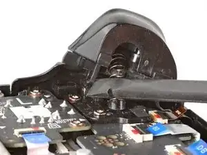
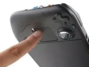
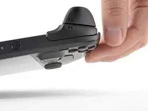
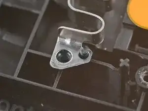
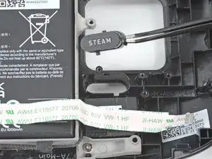
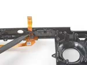
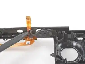
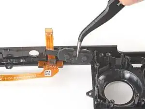
Posiziona la parte piatta di uno spudger sul lato interno del gancio sinistro del grilletto.
-
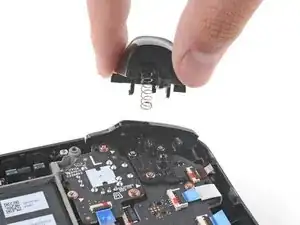
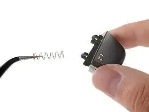
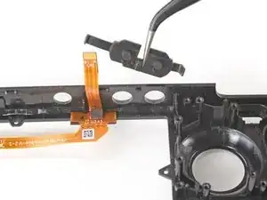
Ruota il gancio del grilletto verso l'esterno e verso l'alto rispetto al perno per sganciarlo.
-
-
-
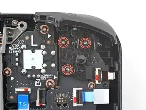
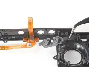
Usa un cacciavite a croce Phillips per rimuovere le tre viti da 5,2 mm che tengono ferma la staffa del grilletto sinistro.
-
-
-
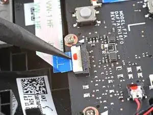
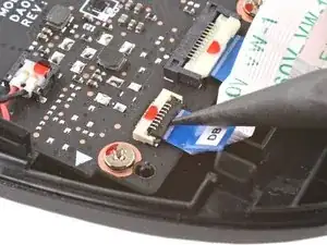
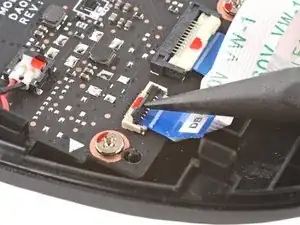
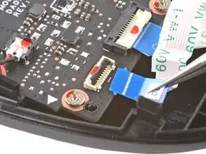
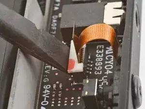
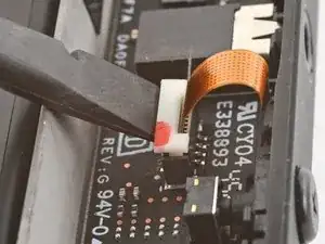
Usa la punta di uno spudger per sollevare l'aletta di bloccaggio sul connettore ZIF del cavo della levetta analogica.
-
Usa un paio di pinzette per far scorrere il cavo via dal suo connettore.
-
-
-
Usa un cacciavite a croce Phillips per rimuovere le tre viti da 5,2 mm che tengono ferma la levetta.
-
-
-
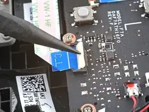
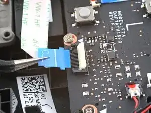
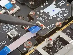
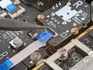
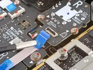
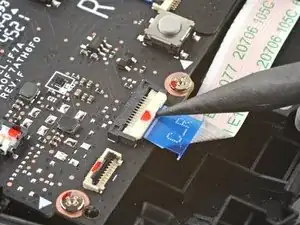
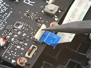
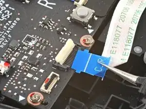
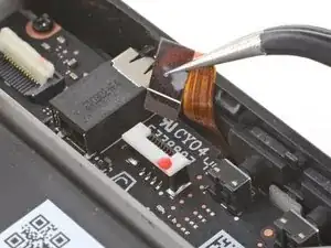
Usa la punta di uno spudger per sollevare l'aletta di bloccaggio del connettore ZIF del cavo di interconnessione della scheda dei pulsanti.
-
Usa un paio di pinzette per far scorrere il cavo via dal suo connettore.
-
-
-
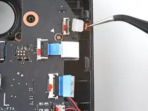
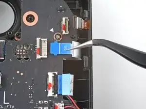
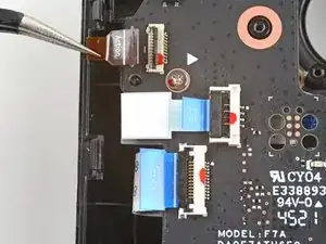
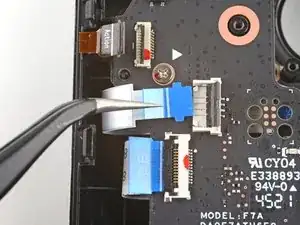
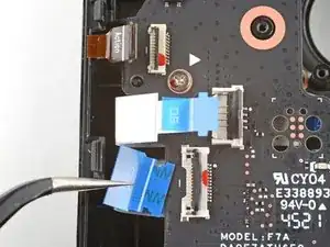
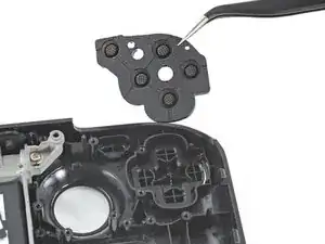
Se alcuni connettori sono coperti da nastro adesivo, utilizza una pinzetta per rimuoverlo.
-
Usa la punta di uno spudger per sollevare le alette di bloccaggio del resto dei connettori ZIF della scheda dei pulsanti. Usa un paio di pinzette per far scorrere i cavi via dai loro connettori:
-
Scollega il cavo del D-pad.
-
Scollega il cavo della scheda del trackpad.
-
Scollega il cavo del trackpad.
-
-
-
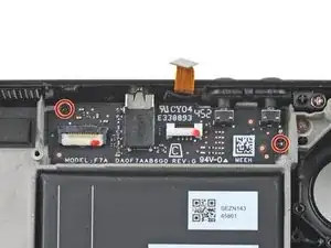
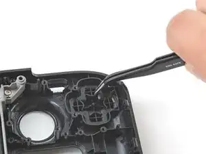
Usa un cacciavite a croce Phillips per scollegare le quattro viti che tengono ferma la scheda dei pulsanti:
-
Tre viti da 5,2 mm
-
Una vite da 3,9 mm
-
-
-
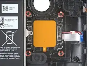
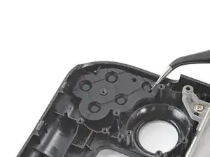
Usa un cacciavite a croce Phillips per rimuovere le quattro viti da 4,7 mm che tengono ferma la scheda del trackpad.
-
-
-
Usa un cacciavite a croce Phillips per rimuovere le quattro viti da 4,7 mm che tengono fermo il trackpad.
-
-
-
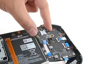
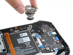
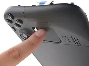
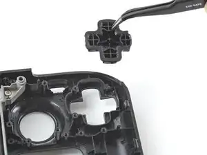
Dal lato anteriore dello Steam Deck, usa le dita per spingere il trackpad sinistro parzialmente attraverso la scocca frontale per rimuoverlo dal suo alloggio.
-
Solleva il trackpad dal sotto la sezione sporgente del telaio intermedio.
-
Rimuovi il trackpad.
-
-
-
Posiziona la parte piatta di uno spudger sul lato interno del gancio destro del grilletto.
-
Ruota il gancio del grilletto verso l'esterno e verso l'alto rispetto al perno per sganciarlo.
-
-
-
Usa un cacciavite a croce Phillips per rimuovere le tre viti da 5,2 mm che tengono ferma la staffa del grilletto destro.
-
-
-
Rimuovi la staffa del grilletto destro.
-
I grilletti di ricambio richiedono la calibrazione per funzionare come previsto. Per calibrare i nuovi grilletti, segui questa guida di calibrazione.
-
-
-
Usa la punta di uno spudger per sollevare l'aletta di bloccaggio sul connettore ZIF del cavo della levetta analogica.
-
Usa un paio di pinzette per far scorrere il cavo via dal suo connettore.
-
-
-
Usa un cacciavite a croce Phillips per rimuovere le tre viti da 5,2 mm che tengono ferma la levetta.
-
-
-
Usa la punta di uno spudger per sollevare l'aletta di bloccaggio sul connettore ZIF del cavo della scheda dei pulsanti.
-
Usa un paio di pinzette per far scorrere il cavo via dal suo connettore.
-
-
-
Usa la punta di uno spudger per sollevare l'aletta di bloccaggio sul connettore ZIF del cavo di interconnessione della scheda dei pulsanti sulla scheda dei pulsanti.
-
Usa un paio di pinzette per far scorrere il cavo via dal suo connettore.
-
-
-
Se alcuni connettori sono coperti da nastro adesivo, utilizza una pinzetta per rimuoverlo.
-
Usa la punta di uno spudger per sollevare le alette di bloccaggio del resto dei connettori ZIF della scheda dei pulsanti. Usa un paio di pinzette per far scorrere i cavi via dai loro connettori.
-
Scollega il cavo dei pulsanti A/B/X/Y.
-
Scollega il cavo della scheda del trackpad.
-
Scollega il cavo del trackpad.
-
-
-
Usa un cacciavite a croce Phillips per scollegare le quattro viti che tengono ferma la scheda dei pulsanti:
-
Tre viti da 5,2 mm
-
Una vite da 3,9 mm
-
-
-
Usa un cacciavite a croce Phillips per rimuovere le quattro viti da 4,7 mm che tengono ferma la scheda del trackpad.
-
-
-
Usa un cacciavite a croce Phillips per rimuovere le quattro viti da 4,7 mm che tengono fermo il trackpad.
-
-
-
Dal lato anteriore dello Steam Deck, usa le dita per spingere il trackpad destro parzialmente attraverso la scocca frontale per rimuoverlo dal suo alloggio.
-
Solleva il trackpad dal sotto la sezione sporgente del telaio intermedio.
-
Rimuovi il trackpad.
-
-
-
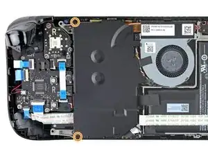
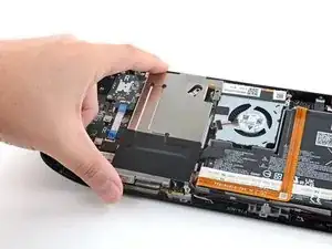
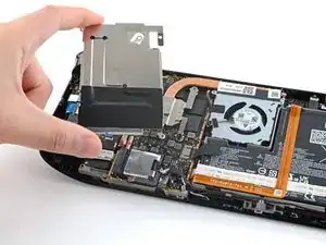
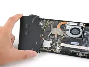
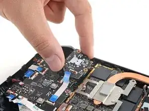
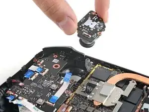
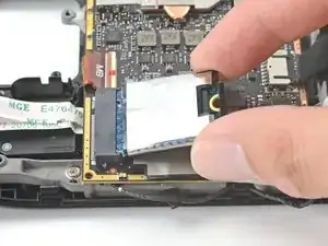
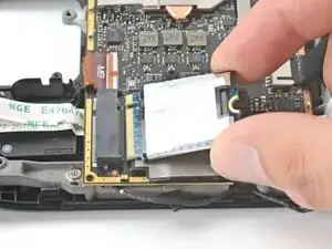
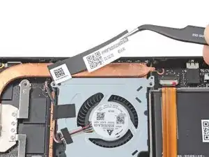
Afferra l'estremità dell'SSD e tiralo via dal suo connettore M.2 sulla scheda madre per rimuoverlo.
-
-
-
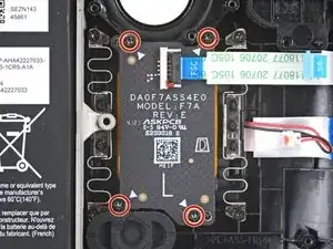
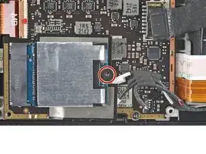
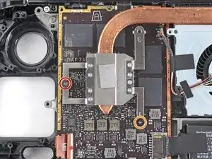
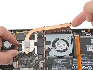
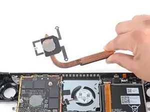
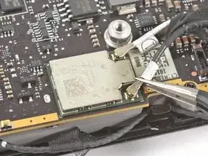
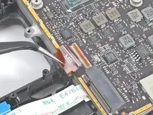
Usa un cacciavite a croce Phillips per svitare e rimuovere le due viti che fissano il dissipatore alla scheda madre:
-
Una vite prigioniera da 3,5 mm
-
Una vite da 3,4 mm
-
-
-
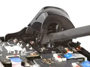
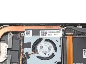
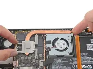
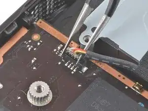
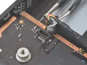
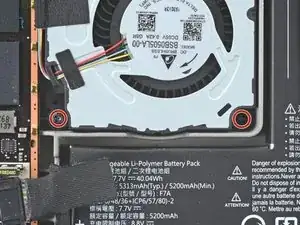
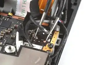
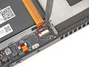
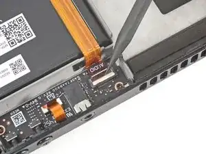
Usa un paio di pinzette per afferrare i bordi del connettore della ventola e tira su per disconnetterlo dalla scheda madre.
-
-
-
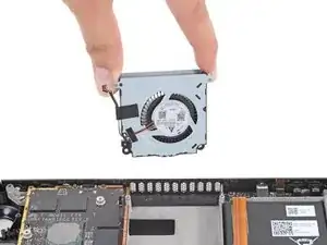
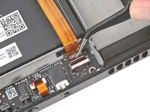
Usa un cacciavite a croce Phillips per rimuovere le due viti da 3,7 mm che tengono ferma la ventola.
-
-
-
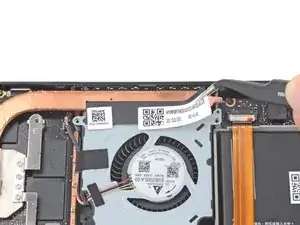
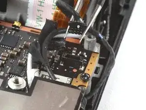
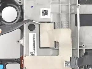
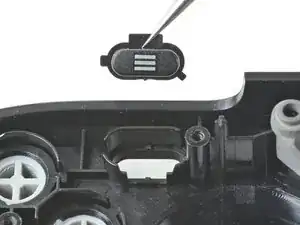
Usa un paio di pinzette per afferrare i bordi del connettore degli altoparlanti e sollevalo per scollegarlo dalla scheda madre.
-
-
-
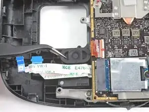
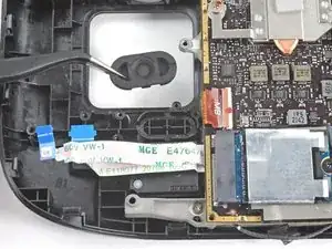
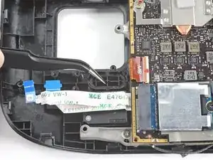
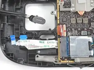
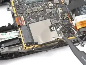
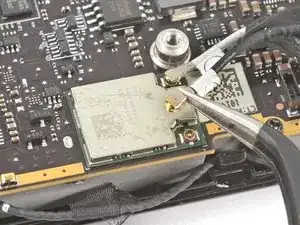
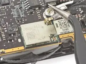
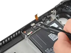
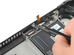
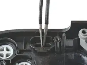
Usa un paio di pinzette per prendere il connettore dell'antenna vicino alla sua base.
-
Tira verso l'alto per scollegare il cavo.
-
Ripeti per il secondo cavo dell'antenna.
-
-
-
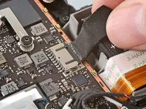
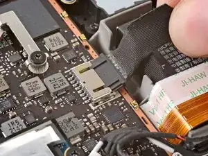
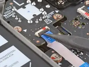
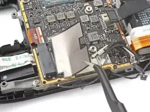
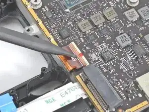
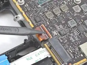
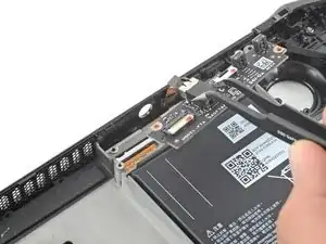
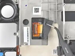
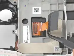
Usa la punta di uno spudger per sollevare l'aletta di bloccaggio sul connettore ZIF del cavo dello schermo.
-
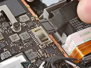
Usa un paio di pinzette per far scorrere il cavo via dal suo connettore.
-
-
-
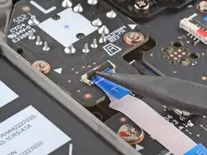
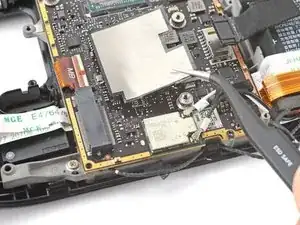
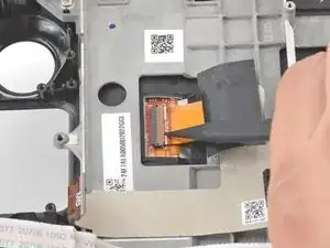
Usa la punta di uno spudger per sollevare l'aletta di bloccaggio sul connettore ZIF del cavo audio.
-
-
-
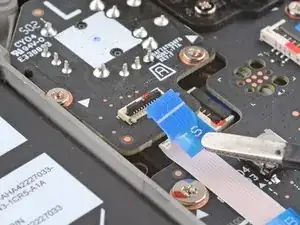
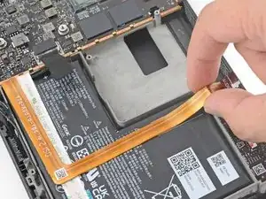
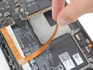
Rimuovi con attenzione il cavo dalla batteria.
-
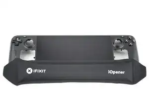
Se l'adesivo è tenace, non forzare il cavo. Scalda leggermente il cavo audio usando un iOpener o un asciugacapelli per ammorbidire l'adesivo.
-
-
-
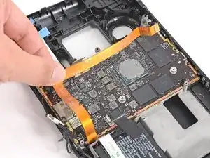
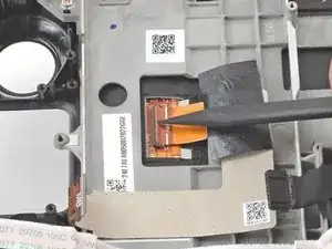
Usa un cacciavite a croce Phillips per rimuovere le tre viti da 3,7 mm che tengono ferma la scheda madre.
-
-
-
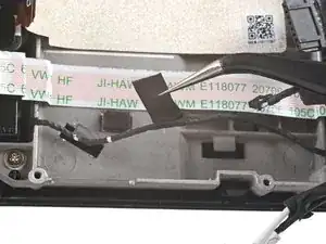
Usa la punta di uno spudger per sollevare l'aletta di bloccaggio bianca del cavo del microfono.
-
Usa un paio di pinzette per tirare il cavo del microfono verso l'alto e fuori dal connettore.
-
-
-
Usa un cacciavite a croce Phillips per rimuovere le due viti da 3,7 mm che tengono ferma la scheda audio.
-
-
-
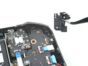
Usa un paio di pinzette per afferrare la scheda audio dal jack cuffie.
-
Ruota la scheda verso l'alto e allontanala dal suo alloggio per rimuoverla.
-
-
-
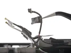
Usa un paio di pinzette per rimuovere il nastro adesivo che raggruppa il cavo dell'altoparlante ai cavi dell'antenna Wi-Fi.
-
-
-
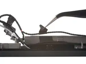
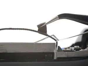
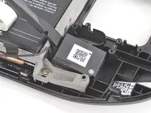
Usa un paio di pinzette per rimuovere le varie strisce di nastro adesivo nero che tengono il cavo dell'altoparlante in posizione lungo il bordo della cornice.
-
-
-
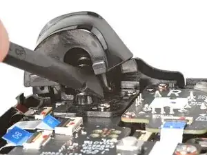
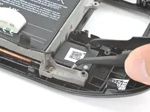
Inserisci la parte piatta di uno spudger tra l'altoparlante destro e la cornice.
-
Inclina lo spudger verso l'alto per separare l'altoparlante dall'adesivo leggero che lo fissa contro la scocca anteriore.
-
-
-
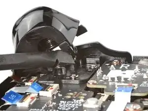
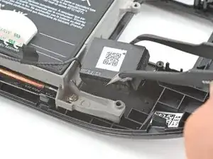
Inserisci la parte piatta di uno spudger tra l'altoparlante destro e la cornice.
-
Inclina lo spudger verso l'alto per separare l'altoparlante dall'adesivo leggero che lo fissa contro la scocca anteriore.
-
-
-
Usa la punta di uno spudger per sollevare l'aletta di bloccaggio sul connettore ZIF del cavo dello schermo.
-
Usa un paio di pinzette per far scorrere il cavo via dal suo connettore.
-
-
-
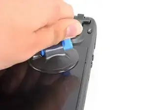
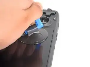
Applica una ventosa all'angolo in alto a sinistra dello schermo premendola per farle fare presa il più vicino possibile al bordo.
-
Tira la ventosa con una forza costante per creare una fessura tra lo schermo e la cornice.
-
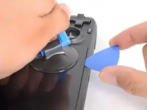
Inserisci la punta di un plettro di apertura nella fessura.
-
-
-
Fai scorrere il plettro di apertura con una profondità inferiore ai 3 mm lungo il bordo superiore per tagliare l'adesivo.
-
-
-
Scalda il bordo sinistro dello schermo per un minuto.
-
Fai scorrere il plettro di apertura lungo il bordo sinistro per tagliare l'adesivo.
-
-
-
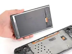
Una volta che hai tagliato intorno al perimetro dello schermo, solleva con attenzione il bordo destro, aprendolo come un libro.
-
Rimuovi lo schermo.
-
-
-
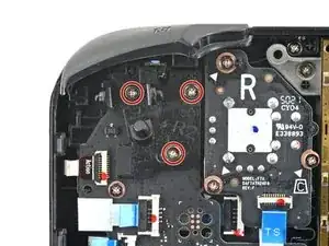
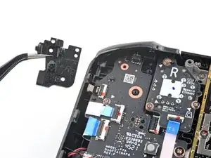
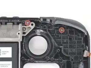
Usa un cacciavite a croce Phillips per rimuovere le due viti da 5,2 mm che tengono fermo il gruppo del pulsante dorsale sinistro.
-
-
-
Usa un cacciavite a croce Phillips per rimuovere le due viti da 5,2 mm che tengono fermo il gruppo del pulsante dorsale destro.
-
-
-
Usa un cacciavite a croce Phillips per rimuovere le sei viti da 2,3 mm che fissano il telaio intermedio alla scocca anteriore, posizionata sul lato anteriore.
-
-
-
Usa un cacciavite a croce Phillips per rimuovere le quattro viti da 5,2 mm che fissano il telaio intermedio alla scocca anteriore.
-
-
-
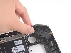
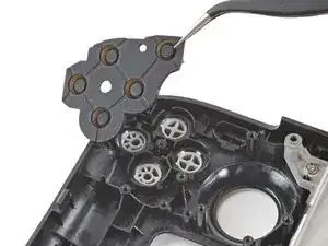
Usa la punta di uno spudger per sollevare l'aletta di gomma a sinistra dei pulsanti del volume verso l'alto e fuori dal suo gancio di plastica.
-
-
-
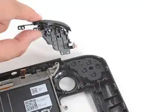
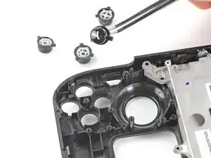
Usa un paio di pinzette per rimuovere i pulsanti del volume tirandoli verso l'alto e lontano dalla scocca anteriore.
-
-
-
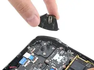
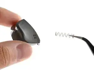
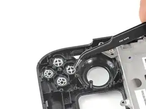
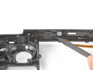
Usa la punta di uno spudger per sollevare l'aletta di gomma a destra del pulsante di accensione verso l'alto e via dal suo gancio di plastica.
-
-
-
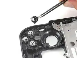
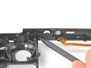
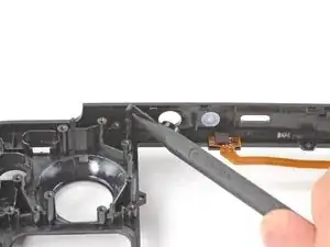
Usa la punta di uno spudger per sollevare l'aletta di gomma a sinistra del pulsante di accensione verso l'alto e via dal suo gancio di plastica.
-
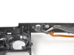
Rimuovi il pulsante di accensione.
-
-
-
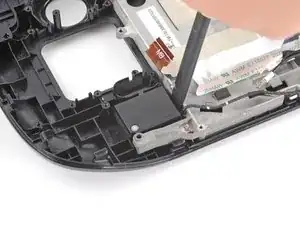
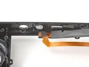
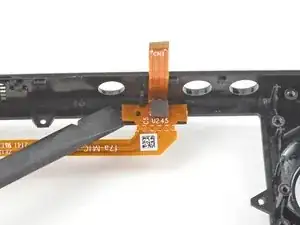
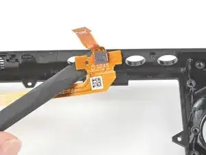
Inserisci la parte piatta di uno spudger sotto l'estremità sinistra del cavo del microfono e fai leva verso l'alto per rimuoverlo dalla scocca anteriore.
-
Se l'adesivo è tenace, non forzare il cavo. Scalda leggermente il cavo del microfono usando un iOpener o un asciugacapelli per ammorbidire l'adesivo.
-
-
-
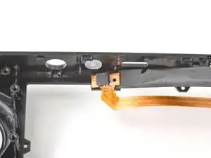
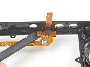
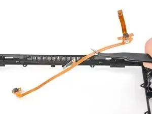
Inserisci la parte piatta di uno spudger sotto l'estremità destra del cavo del microfono e fai leva verso l'alto per rimuoverlo dalla scocca anteriore.
-
Se l'adesivo è tenace, non forzare il cavo. Scalda leggermente il cavo del microfono usando un iOpener o un asciugacapelli per ammorbidire l'adesivo.
-


Per rimontare il dispositivo, segui le istruzioni in ordine inverso.
Porta i tuoi rifiuti elettronici a un riciclatore certificato R2 o e-Stewards.
La riparazione non è andata secondo i piani? Prova delle soluzioni ai problemi di base o chiedi alla nostra comunità Risposte Steam Deck per trovare aiuto.

16 commenti
maybe I don’t need an Atomic Purple replacement shell…
Jon -
Hahaha. Same
Rob -
Same, wouldn't have minded a sweet water dipped or translucent outer shell. Bring back that mad catz/third party aesthetic.
I wanted to replace my old shell with a new one cause it got scratches... well, now I feel the scratches ain't that ugly.
Seems to me like a "Welp...I guess if I ever break the screen and have to replace it, that's when I'll get an atomic purple shell...
I dropped mine and scratched it.... This seems to involve more than a simple screen replacement on my phones. I'll likely still order some spare parts just in case. With a baby on the way, they will likely break it and I want to be able to fix it quickly.
Fortunately, mine at the moment works. I should always close the hard case. Took it out of the car and didn't zip it up. Fell right out.
Just fell down the stairs and the joysticks damaged the top shell, but everything still works. After reading this, I think I'm going to live with it. Sheesh.